COMPONENT_CYLINDER
Mesh commands
*COMPONENT_CYLINDER
"Optional title"
coid, pid, N${}_1$, N${}_2$, csysid, symmetry
$x_1$, $y_1$, $z_1$, $x_2$, $y_2$, $z_2$, $R_1$, $R_2$
"Optional title"
coid, pid, N${}_1$, N${}_2$, csysid, symmetry
$x_1$, $y_1$, $z_1$, $x_2$, $y_2$, $z_2$, $R_1$, $R_2$
Parameter definition
Variable
Description
coid
Component ID
pid
Part ID
N${}_1$
Number of elements in axial direction
N${}_2$
Mesh density parameter
csysid
Local coordinate system ID
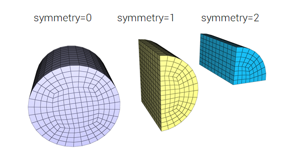
symmetry
Optional command to define a half or quarter symmetry cylinder
$x_1$, $y_1$, $z_1$
Face center coordinate 1
$x_2$, $y_2$, $z_2$
Face center coordinate 2
$R_1$
Radius at face 1
$R_2$
Radius at face 2
Description
This command is used to define a solid cylinder with part ID pid.
Example
Full, half and quarter symmetry cylinder components
A simple example showing how to define cylinder components.
*PARAMETER
symm_full = 0
symm_half = 1
symm_qrtr = 2
*COMPONENT_CYLINDER
"full"
1, 1, 10, 8, 0, [%symm_full]
0, 0, 0, 0, 0, 1, 0.5
*COMPONENT_CYLINDER
"half"
2, 2, 10, 8, 0, [%symm_half]
1, 0, 0, 1, 0, 1, 0.5
*COMPONENT_CYLINDER
"quarter"
3, 3, 10, 8, 0, [%symm_qrtr]
2, 0, 0, 2, 0, 1, 0.5
*MAT_RIGID
1, 7800.0
*PART
"full"
1, 1
"half"
2, 1
"quarter"
3, 1
*END
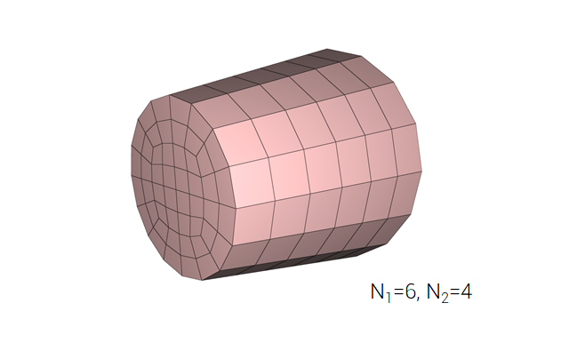
Define a tapered cylinder component
Definition of a tapered cylinder with component ID 100 and part ID 200.
*COMPONENT_CYLINDER
"tapered cylinder"
100, 200, 6, 4
0, 0, 0, 0, 0, 1, 0.4, 0.6
*MAT_RIGID
300, 2700.0
*PART
"tapered cylinder"
200, 300
*END