WELD
Mesh commands
nsid, stype, pid, nseg, $a$, $roff$
Parameter definition
Description
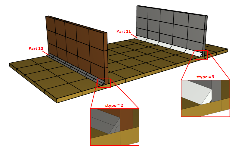
This command is used to generate the mesh of a weld seam. The solver terminates immediately after outputting the generated grid to the file weld.k. The weld seam is to be connected to the welded parts with the MERGE command. The mechanical properties in the heat affected zone (HAZ) can be accounted for by importing results from WeldSim (TM) through the command INITIAL_STATE_WELDSIM, or by manually defing properties through INITIAL_STATE_HAZ. Note that a weld root offset ($roff > 0$) requires a 1-quad section (stype = 3). The 1-quad section is not allowed if $roff = 0$.
Example
Weld 1
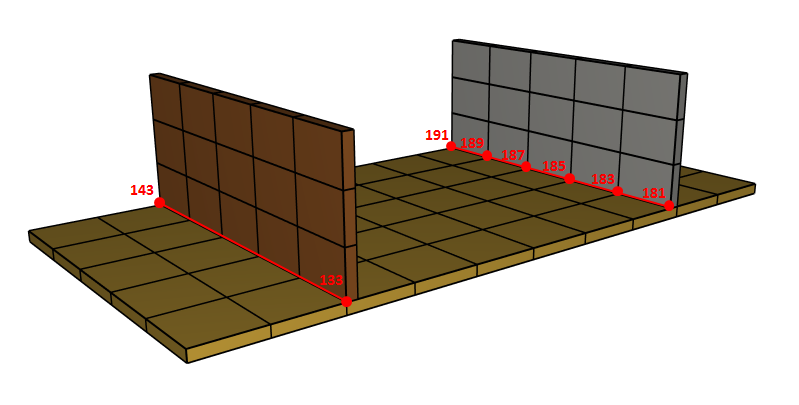
The commands below define two simple weld seams that are stored in weld.k under part ID's 10 and 11.
Weld 2
The weld geometry in weld.k can be merged with the original input using the INCLUDE command.