
CHANGE_P-ORDER
Nodes and connectivity
*CHANGE_P-ORDER
"Optional title"
entype, enid, order, gid
"Optional title"
entype, enid, order, gid
Parameter definition
Variable
Description
entype
Entity type
enid
Entity identification number
order
New element polynomial order
gid
ID of a GEOMETRY that defines a sub-space for change of polynomial order
Description
Change element polynomial order in a selected region of a part or part set.
Example
Change of polynomial order
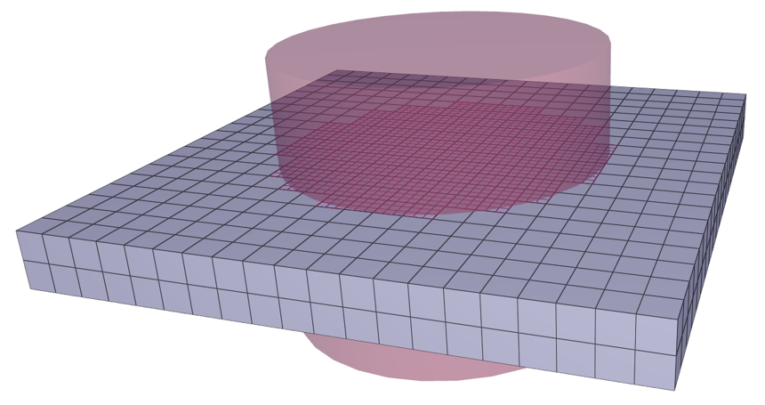
The following command defines a region in space where linear elements are converted to cubic.
*COMPONENT_BOX
1, 1, 20, 20, 2
0, 0, 0.45, 1, 1, 0.55
*PART
1, 1
*MAT_RIGID
1, 7800
*CHANGE_P-ORDER
P, 1, 3, 123
*GEOMETRY_PIPE
123
0.5, 0.5, 0.25, 0.5, 0.5, 0.75, 0.3
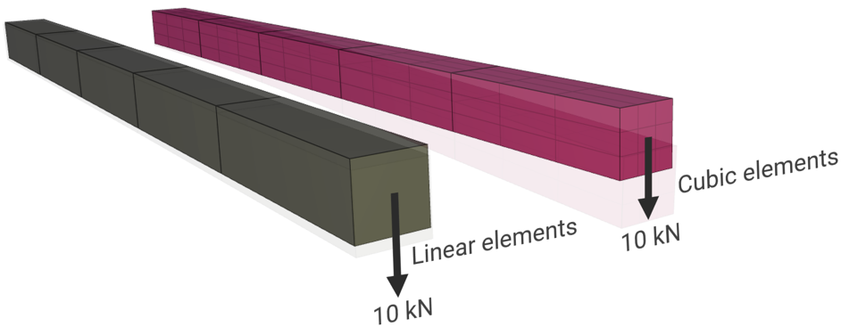
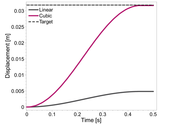
Linear vs. cubic elements
Two cantilever beams are subjected to a transverse point load at the unconstrained end. One of the beams is modeled with five LHEX (Linear hexagonal) elements and the other with five CHEX (Cubic hexagonal) elements. From Euler-Bernoulli beam theory, the maximum deflection, $\mathbf\delta_{max}$ is:
$\mathbf\delta_{max} = \displaystyle{ \frac{PL^3}{3EI} } = \displaystyle{ \frac{1.0e4 \cdot 1.0^3}{3 \cdot 200e9 \cdot \frac{0.05 \cdot 0.05^3}{12}} = 32 mm}$
where, $P$ is the applied load, $L$ is the length of the beam, $E$ is the elastic modulus and $I$ is the moment of inertia. The higher order elements are superior to the linear elements for this model setup.
*PARAMETER
%tend = 0.5, "Termination time"
%l = 1.0, "Length of the beam"
%t = 0.05, "Thickness of the beam"
%d = 0.1, "Distance value"
%F_max = 1e4, "Load applied"
*TIME
[%tend]
*OUTPUT
[%tend/5]
*UNIT_SYSTEM
SI
*COMPONENT_BOX
"Linear elements"
1, 1, 5, 1, 1
0, 0, [-%d], [%l], [%t], [%t - %d]
*COMPONENT_BOX
"Cubic elements"
2, 2, 5, 1, 1
0, 0, [%d], [%l], [%t], [%t + %d]
*MAT_ELASTIC
1, 7800, 200e9, 0.3
*CHANGE_P-ORDER
P, 2, 3
*PART
1, 1
2, 1
#Fixed ends
*BC_MOTION
1
G, 1, XYZ
*GEOMETRY_SEED_COORDINATE
1
0, [%t/2], [%t/2 - %d]
*BC_MOTION
2
G, 2, XYZ
*GEOMETRY_SEED_COORDINATE
2
0, [%t/2], [%t/2 + %d]
# Prescribed force
*LOAD_FORCE
11
G, 11, Y, 10
*GEOMETRY_SEED_COORDINATE
11
[%l], [%t/2], [%t/2 - %d]
*LOAD_FORCE
12
G, 12, Y, 10
*GEOMETRY_SEED_COORDINATE
12
[%l], [%t/2], [%t/2 + %d]
*FUNCTION
10
smooth_d(%F_max, 0, 0.9*%tend)
*OUTPUT_SENSOR
"Linear"
1, 1, [%l], [%t/2], [%t/2 - %d]
*OUTPUT_SENSOR
"Cubic"
2, 2, [%l], [%t/2], [%t/2 + %d]
*CURVE
"Target"
10000
[0.0*%tend], 0.032
[1.0*%tend], 0.032
*END