INITIAL_MATERIAL_DIRECTION_PATH
Initial conditions
"Optional title"
coid, entype, enid, pathid
Parameter definition
Description
This command is used to define local material directions in components that are modeled with one single element in thickness direction. For each element the nearest point along the PATH is identified. The PATH direction at this point defines a first estimate of the local 0-degree fiber direction $\bar{\mathbf x}$. The 90-degree direction is obtained as the cross product between the surface normal $\hat{\mathbf n}$ and the estimated 0-degree direction.
$\displaystyle{ \hat{\mathbf y} = \frac{\hat{\mathbf n} \times \bar{\mathbf x}}{\vert \hat{\mathbf n} \times \bar{\mathbf x} \vert}}$
The final 0-degree direction $\hat{\mathbf x}$ is computed as:
$\displaystyle{ \hat{\mathbf x} = \frac{\hat{\mathbf y} \times \hat{\mathbf n}}{\vert \hat{\mathbf y} \times \hat{\mathbf n} \vert}}$
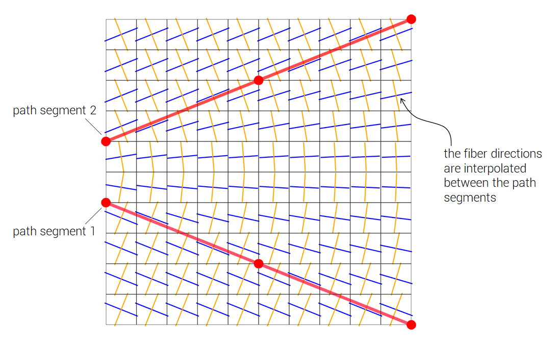
The PATH can be subdivided into several segments. A split is made wherever the local $x$-coordinate is set to $1.0E20$. If split, then the local fiber directions are defined by interpolating between the two nearest path segments (see example below).
Example
Material fiber directions
An example where the path is split into two segments. The fiber directions are interpolated between the segments.