LOAD_AIR_BLAST

Loads
*LOAD_AIR_BLAST
"Optional title"
coid
entype, enid, $mtnt$, $x_c$, $y_c$, $z_c$, tid, diffract
toff, ground, $t_{end}$
Parameter definition
VariableDescription
coid Command ID
entype Entity type
options: P, PS, ALL
enid Entity ID
$mtnt$ Charge size (kg TNT equivalent)
$x_c$ Charge location (x-coordinate)
$y_c$ Charge location (y-coordinate)
$z_c$ Charge location (z-coordinate)
tid ID of TABLE defining reflective surfaces
diffract Diffraction level
options:
0 $\rightarrow$ no diffraction
1 $\rightarrow$ diffraction around one corner
2 $\rightarrow$ diffraction around two corners
default: no diffraction
toff Time offset flag
options:
0 $\rightarrow$ no offset
1 $\rightarrow$ time of arrival is offset to t=0
ground Reflecting ground
options: X, Y, Z
default: no ground
$t_{end}$ Deactivation time
default: not used
Description

This command is used to define an air blast load from a spherical charge. It is based on semi-empirical equations according to Kingery-Bulmash. The implementation includes options to account for diffraction and ground reflections.

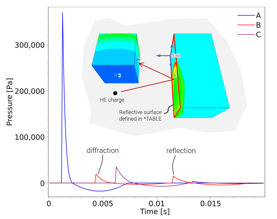
There is also an option that allows for reflections against rectangular surfaces. These surfaces need to be defined in a separate TABLE. An example is included below. (The reason for not working directly with reflections against the Finite Element mesh is to prevent unwanted effects from local geometrical features.)

Example
Blast loaded wall

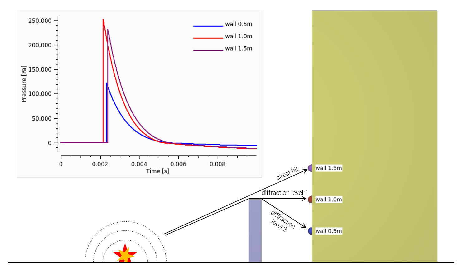
This examples displays the effect of diffraction. Two of the sensors are not in the direct line of sight from the explosive charge. By activating the diffraction option, the blast wave travels around the obstacle edges and eventually reaches the initially shielded sensors.

*UNIT_SYSTEM
SI
#
# --- TIME ---
#
*TIME
0.01, 0, 0, 1.0e-5
#
# --- SENSORS ---
#
*OUTPUT_SENSOR
"wall 0.5m"
2, 2, 3, 0, 0.5
"wall 1.0m"
3, 2, 3, 0, 1
"wall 1.5m"
4, 2, 3, 0, 1.5
#
# --- MESH ---
#
*COMPONENT_BOX
"obstacle"
1, 1, 1, 10, 5
2, -1, 0, 2.2, 1, 1
*COMPONENT_BOX
"house"
2, 2, 10, 10, 20
3, -1, 0, 5, 1, 4
#
# --- MATERIAL ---
#
*MAT_RIGID
1, 1000.0
#
# --- PART ---
#
*PART
"obstacle"
1, 1
"house"
2, 1
#
# --- BC ---
#
*BC_MOTION
"obstacle"
1
P, 1, XYZ, XYZ
*BC_MOTION
"house"
2
P, 2, XYZ, XYZ
#
# --- BLAST LOAD ---
#
*LOAD_AIR_BLAST
1
ALL, 0, 1, 0, 0, 0, 0, 2
1, Z
*END
Reflection

In this example a reflective surface is defined. The pressure wave against the wall of sensor C reflects and hits the wall where sensor B is located. Sensor B registers two pressure signals, the first due to diffraction around the corner of the face where sensor A is located. The second peak is from the reflected wave.

*UNIT_SYSTEM
SI
*PARAMETER
mtnt = 0.1, "charge size"
*TIME
0.02, 0, 0, 1.0e-4
#
# --- SENSORS ---
#
*OUTPUT_SENSOR
"A"
1, 1, 0, 1, 1
"B"
2, 1, 1, 2, 1
"C"
3, 2, 3, 1, 1
#
# --- MESH ---
#
*COMPONENT_BOX
"house A"
1, 1, [%N], [%N], [%N]
-1, 1, 0, 1, 3, 2
*COMPONENT_BOX
"house B"
2, 2, [%N], [2*%N], [%N]
3, -1, 0, 5, 3, 2
#
# --- MATERIAL ---
#
*MAT_RIGID
1, 2500.0
#
# --- PART ---
#
*PART
"house A"
1, 1
"house B"
#
# --- BLAST LOAD ---
#
*LOAD_AIR_BLAST
1
PS, 12, [%mtnt], 0, 0, 1, 123, 1
Z
*SET_PART
12
1, 2
#
# Col 1: Coordinate system ID
# Col 2: Rectangle width
# Col 3: Rectangle height
*TABLE
"reflective surface"
123, 3
333, 4, 2
*COORDINATE_SYSTEM_FIXED
333, 3, 3, 0
0, -1, 0, 0, 0, 1
*END