
MAT_MMC
Material properties
"Optional title"
mid, $\rho$, $G$
$\sigma_c$, $\sigma_x$, $P_x$, $\sigma_{cap}$, $\alpha$, $\varepsilon_{p,fail}$, $yield$
$K$, $\beta$, $\varepsilon_{v,max}$, $c$, $\dot{\varepsilon}_0$, $\psi$, $d$, $d_{dec}$
Parameter definition
Description
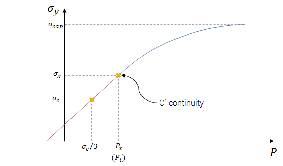
This ceramic model is assumed to have a pressure dependent shear resistance. The pressure dependency is defined by two points on the yield strength vs. pressure curve and an optional cap on the yield strength.
The yield strength vs. pressure curve is defined as a combination of two functions. $C_1$ continuity prevails in the transition between the two functions and the transition is defined at a pressure $P_t$, defined as:
$\displaystyle{P_t = max\left(\frac{\sigma_c}{3}, P_x\right)}$
The yield strength, $\sigma_y$ vs. pressure, $P$, is defined as:
$\sigma_y(P) = \left\{ \begin{array}{cc} \displaystyle{c_1 \cdot P + c_2} &: P \leq P_t\\ \displaystyle{\sigma_{cap} \cdot \left(1.0 - exp\left(-c_3 \cdot P + c_4\right)\right)} &: P \gt P_t \end{array} \right. $
Parameters $c_1$ to $c_4$ are calculated and set in the solver based on given input.
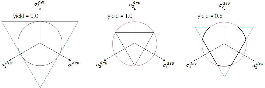
By default, von Mises yield surface is used ($yield = 0.0$). A Rankine surface is defined by setting $yield = 1.0$. Values between $0.0$ and $1.0$ are accepted to achieve a combination of the two surfaces.
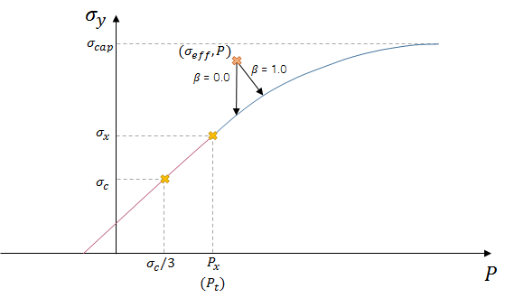
Plastic flow is optional and included by setting $\varepsilon_{p,fail} \gt 0.0$. With zero as input, the material becomes linear-elastic up to failure and the material strength vs. pressure curve coincides with the yield strength vs. pressure curve. Dilatation is optional during plastic flow and limited by $\varepsilon_{v,max}$. Dilatation is included by defining $\beta$ and $\varepsilon_{v,max} \gt 0.0$. Associated plastic flow is achieved with $\beta = 1.0$.
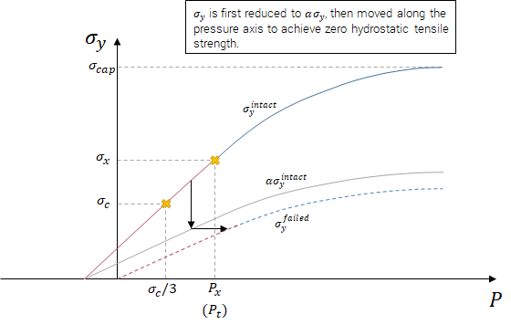
Failed material maintains a fraction of the intact shear resistance, $\alpha$, in the positive pressure regime.
Strain rate effects are included by increasing the quasi-static yield strength by a factor $rfac$, calculated as:
$\displaystyle{rfac = \left(1.0 + \frac{\dot{\varepsilon}^{eff}}{\varepsilon_0}\right)^c}$
With $\psi = 0.0$ (default), the hydrostatic tensile strength is not affected by the strain rate effects. $\psi = 1.0$ means that the hydrostatic tensile strength also is scaled by the factor $rfac$.
Damage, $D$, is a function of the effective plastic strain, $\varepsilon^{eff}_p$, and develops gradually from 0.0 to 1.0:
$\displaystyle{D = min \left(1.0, \frac{\varepsilon^{eff}_p}{\varepsilon_{p,fail}}\right)}$