"Optional title"
coid
entype${}_s$, enid${}_s$, entype${}_m$, enid${}_m$, $tol$, mfid, gid, penalty, $\alpha_{max}$, no_self
Parameter definition
Variable | Description |
---|---|
coid | Command ID (optional) |
entype${}_s$ | Slave entity type |
enid${}_s$ | Slave entity identification number |
entype${}_m$ | Master entity type |
enid${}_m$ | Master entity identification number |
$tol$ | Tolerance for merging (absolute distance) |
mfid | ID of MERGE_FAILURE command |
gid | ID of GEOMETRY defining the region to be merged |
penalty | Flag to switch to penalty formulation |
$\alpha_{max}$ | Maximum allowed deviation from parallelism |
no_self | Flag to deactivate self-merging (same slave and master part ID) |
Description
This command can be used to merge disjointed meshes. Note that the finer element grid should be on the slave side. Interface forces are written to merge.out. Maximum tensile and shear stresses are also output, if a failure criterion has been define (parameter mfid).
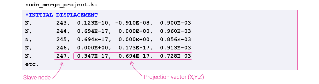
The command generates a file _node_merge_project.k containing INITIAL_DISPLACEMENT projection vectors for all merged slave nodes. The INITIAL_DISPLACEMENT commands can be used to adjust the slave node positions, to be located right on the master faces.
Note SPH sub-domains must me on the save side when merged with finite element surfaces.
Example
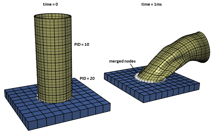
Merge disjointed meshes
A flexible pipe with part ID = 10 is merged to a plate with part ID = 20. The pipe is given an initial velocity of $100 \mathrm{m/s}$. The rigid plate is fixed in space.
# Merge a pipe to a plate - complete input deck
*TIME
0.001
#
# Define geometries and mesh
*COMPONENT_PIPE
"pipe"
10, 10, 10, 10, 1
0.0, 0.0, 0.0, 0.0, 0.0, 0.1, 0.02, 0.021
*COMPONENT_BOX
"plate"
20, 20, 10, 10, 1
-0.05, -0.05, -0.01, 0.05, 0.05, 0.0
*CHANGE_P-ORDER
P, 10, 3
#
# Material properties
*MAT_ELASTIC
10, 1500.0, 1.0e8, 0.49
*MAT_RIGID
20, 7800.0
*PART
"pipe"
10, 10, 0, 0, 45.0
"plate"
20, 20
#
# Boundary and initial conditions
*BC_MOTION
"fixed plate"
P, 20, XYZ, XYZ
*INITIAL_VELOCITY
P, 10, 100.0, 0.0, 0.0
*MERGE
"pipe to plate"
P, 10, P, 20
*END
Merge with initial displacements
A pipe (slave entity) is merged to a box (master entity).
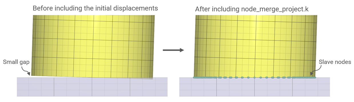
The file _node_merge_project.k is automatically generated when starting the simulation. It is then included to the main file. The node positions of the slave nodes are adjusted with the help of the initial displacements within the included file when rerun. Note that the file name is changed to node_merge_project.k in the example.
SI
#*INCLUDE
#node_merge_project.k
*COMPONENT_BOX
1, 1, 10, 10, 1
-0.1, -0.1, -0.01, 0.1, 0.1, 0
*COMPONENT_PIPE
2, 2, 10, 20, 1
0, 0, 0, 0.003, 0, 0.1, 0.03, 0.032
*CHANGE_P-ORDER
ALL, 0, 3
*SMOOTH_MESH
ALL, 0, 45.0
*MAT_METAL
1, 7800.0, 210.0e9, 0.3
1
*FUNCTION
1
3.0e8 + 3.0e8*epsp^0.3
*PART
"plate"
1, 1
"pipe"
2, 1
*MERGE
P, 2, P, 1, 1.0e-3
*END