OUTPUT_SECTION

Output
*OUTPUT_SECTION
"Optional title"
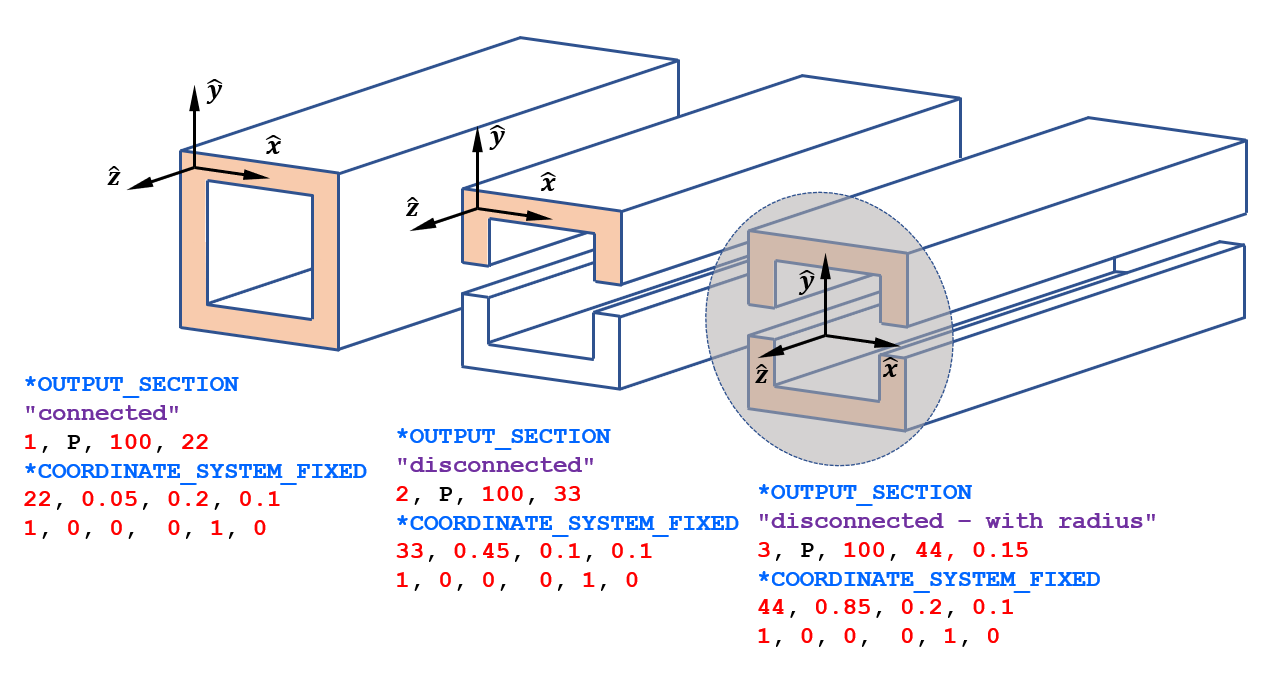
coid, entype, enid, csysid, $R$
Parameter definition
VariableDescription
coid Command ID
entype Entity type
options: P, PS, ALL
enid Entity ID
csysid Local coordinate system ID
$R$ Section radius
default: not used
Description

This command defines a cross section for sampling of forces, bending moment and area.

The local coordinate system is mandatory and defines a point on the cross section. The local $z$-axis is used as the cross section normal direction. The radius $R$ is used to define cross sections consisting of disconnected regions.

Note that the cross section does not need to follow the element grid.

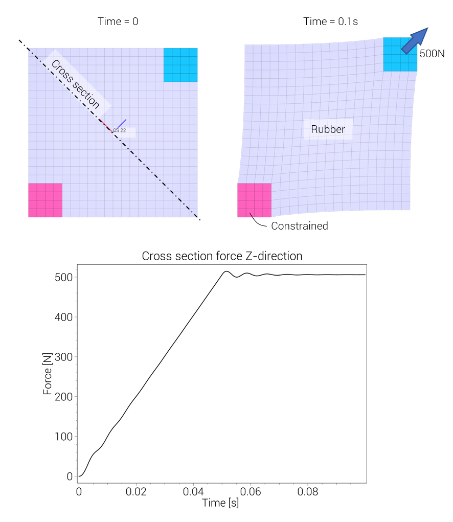
Time history data are written to the file section.out. Forces and bending moments are reported with respect to the local coordinate system. Hence, 'Force in X-direction' and 'Force in Y-direction' are local in-plane forces while 'Force in Z-direction' is the force in the cross section normal direction.

Different cross sections
Example
Cross section cutting diagonally through mesh

A complete model of a rubber sample that gets stretched with a load of 500N. A cross section is defined and the section forces are written to section.out.


*UNIT_SYSTEM
SI
*PARAMETER
L = 0.1, "size of specimen"
X = 0.02, "size of rigid corners"
h = 0.01, "thickness"
*TIME
0.1
*OUTPUT_SECTION
"Diagonal cross section"
1, P, 1, 22
*COORDINATE_SYSTEM_FIXED
22, [%L/2], [%L/2], [%h/2]
-0.70711, 0.70711, 0, 0, 0, 1
#
# --- MESH ---
#
*COMPONENT_BOX
"Rigid corner - lower left"
1, 2, 4, 4, 1
0, 0, 0, [%X], [%X], [%h]
*COMPONENT_BOX
"Rubber 1"
2, 1, 16, 4, 1
[%X], 0, 0, [%L], [%X], [%h]
*COMPONENT_BOX
"Rubber 2"
3, 1, 20, 12, 1
0, [%X], 0, [%L], [%L-%X], [%h]
*COMPONENT_BOX
"Rubber 3"
4, 1, 16, 4, 1
0, [%L-%X], 0, [%L-%X], [%L], [%h]
*COMPONENT_BOX
"Rigid corner - upper right"
5, 3, 4, 4, 1
[%L-%X], [%L-%X], 0, [%L], [%L], [%h]
*MERGE_DUPLICATED_NODES
ALL, 0, ALL, 0, 0.0001
#
# --- MATERIALS ---
#
*MAT_MOONEY_RIVLIN
"Rubber"
1, 1000.0, 1.0e9
1.0e6, 1.0e6, 1.0e3
*MAT_RIGID
"Corners"
2, 7800.0
#
# --- PARTS ---
#
*PART
"Rubber"
1, 1
"Corner - lower left"
2, 2
"Corner - upper right"
3, 2
#
# --- CONSTRAINT AND LOAD ---
#
*BC_MOTION
"Corner - lower left"
1
P, 2, XYZ, XYZ
*LOAD_FORCE
P, 3, Z, 1, 1.0, 22
*FUNCTION
1
1.0e4*min(t, term/2)
*END