PRESTRESS_BOLT
Loads
pid${}_{bolt}$, pid${}_{nut}$, cid, $sf$, $t_{beg}$, $t_{end}$, no_match
Parameter definition
Description
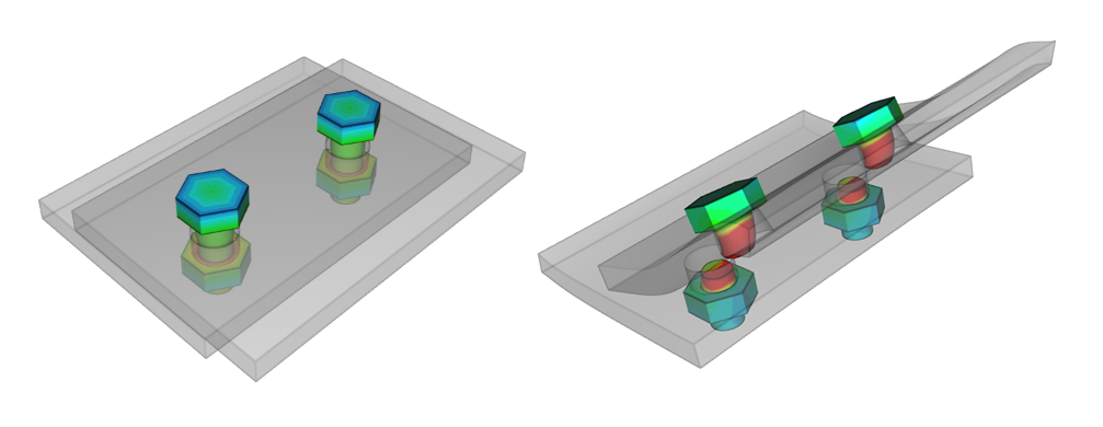
This command is used to pre-stress a set of bolts and to apply balancing forces to the corresponding nuts. pid${}_{bolt}$ is assumed to contain one or several bolts. pid${}_{nut}$ must contain the same number of nuts. The command identifies the discrete bolts and nuts and creates bolt-nut pairs. The bolt shafts are pre-stressed with the axial stress defined by curve cid.
Models with bolted connections need to be run in two steps, where the first step tightens the bolts. When the pre-stressing phase is finished, the model (in its current state) needs to be output to a set of state files. impetus_stateX.k contains the the geometry and information about the contact state. impetus_stateX.bin is a binary file with all element stresses and state variables. Finally, impetus_state_boltX.k contains MERGE commands for each nut/bolt pair. These state files are used as command files for the second step, where the structure is exposed to the loads of interest.
Note that the state file output is defined in the command OUTPUT.
Example
Prestress bolt
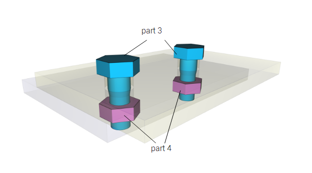
The following commands define an axial bolt shaft stress of 200MPa. The bolts are in part 3 and the nuts in part 4. The applied shaft stress ramps up from 0 to 200MPa in 1ms and is then held constant.
The OUTPUT command is defined to output state files for the complete model at termination. These state file are to be included in the next modeling stage, where the nuts are clamped to the bolt shafts and the structure can be exposed to the desired load case:
impetus_state_boltX.k contains MERGE commands that lock the nuts to the bolts:
Each bolt/nut pair has its own MERGE definition. As a consequence merge.out will have one force history curve for each bolt/nut pair.