
PROP_DAMAGE_HC
Material properties
"Optional title"
did, erode, noic
$a$, $b$, $c$, $n$, $T_a$, $T_b$, $\sigma_s$, $t_s$
$\alpha_s$, $c_r$, $\dot\varepsilon_r$, $G_I$
Parameter definition
Description
This is a slightly modified version of Hosford-Coulomb ductile failure criterion. The original model has been extended with two parameters $(T_a, T_b)$, allowing for the definition of a temperature dependent ductility.
The material will fail once the damage parameter, $D$, has evolved from 0 to 1. The damage growth rate is defined as:
$\displaystyle{ \dot D = \frac{\dot\varepsilon_{eff}^p}{\varepsilon_f}}$
where:
$\displaystyle{ \varepsilon_f = b \left( \frac{1+c}{g(\eta,\theta)} \right)^{1/n} \cdot \left( 1 + \frac{\dot\varepsilon_{eff}^p}{\dot\varepsilon_r} \right)^{c_r} \cdot \mathrm{max} \left( 1, e^{\frac{T-T_a}{T_b}} \right) }$
$g(\eta,\theta)$ is a function of stress triaxiality $\eta$ and Lode angle parameter $\theta$.
$\displaystyle{g(\eta,\theta) = \left( \frac{1}{2}\vert f_I-f_{II} \vert^a + \frac{1}{2}\vert f_{II}-f_{III} \vert^a + \frac{1}{2}\vert f_{III}-f_I \vert^a \right)^{1/a} + c \left( 2\eta + f_I + f_{III} \right)}$
$\displaystyle{ f_I(\theta) = \frac{2}{3} \mathrm{cos} \left( \frac{\pi}{6}(1-\theta) \right) }$
$\displaystyle{ f_{II}(\theta) = \frac{2}{3} \mathrm{cos} \left( \frac{\pi}{6}(3+\theta) \right) }$
$\displaystyle{ f_{III}(\theta) = -\frac{2}{3} \mathrm{cos} \left( \frac{\pi}{6}(1+\theta) \right) }$
The ductile failure criterion is complemented with an optional spall criterion. Spall fracture occurs when a spall damage parameter $D_s$ evolves from from 0 to 1.
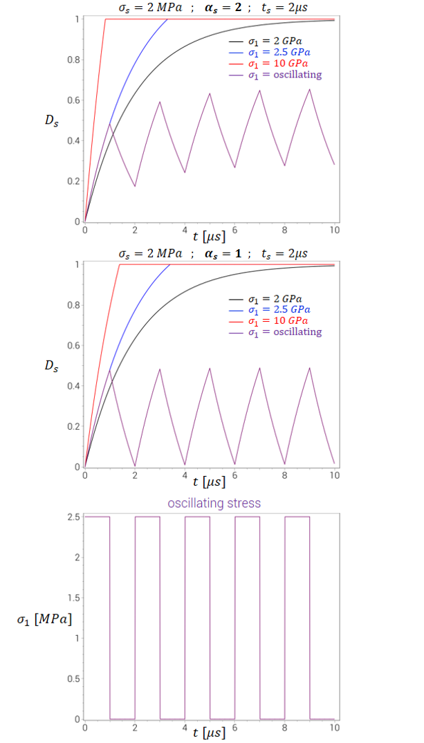
$ \dot{D}_s = \left\{ \begin{array}{ccc} \frac{1}{t_s}\left(\frac{\sigma_1}{\sigma_s}-D_s\right) & : & \sigma_1 \leq \sigma_s \\ \frac{1}{t_s} \left(1 + \alpha_s \left(1 - \mathrm{e}^{-\frac{\sigma_1 - \sigma_s}{\alpha_s \sigma_s}} \right) - D_s\right) & : & \sigma_1 \gt \sigma_s \\ \end{array} \right. $
Note that the spall damage parameter $D_s$ is not necessarily monotonically growing. It grows if the first princial stress $\sigma_1$ is large and drops is $\sigma_1$ is small. The main purpose of this unconventional formulation is to filter numerical noise (such as stress oscillations from element erosion in contact interfaces).
The figure below exemplifies how the spall damage parameter grows at different stress levels (for two different $\alpha_s$).
The optional fracture energy parameter $G_I$ is used for a better prediction of the crack propagation process. The parameter is only used when having node splitting activated and when combined with either MAT_METAL or MAT_HSS.