SUBDIVIDE_PART_THICKNESS

Mesh commands
*SUBDIVIDE_PART_THICKNESS
"Optional title"
coid
pid, tid, $x_f$, $y_f$, $z_f$, absolute
Parameter definition
VariableDescription
coid Command ID
pid Part ID
tid Table ID
$x_f$, $y_f$, $z_f$ Coordinate on front face
absolute Flag for absolute layer thicknesses in table
options:
0 $\rightarrow$ relative thicknesses
1 $\rightarrow$ absolute thicknesses
Description

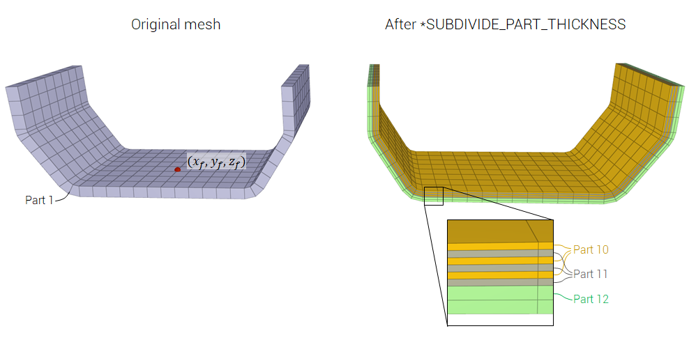
This command is used to subdivide a structure into multiple layers. The original mesh can be curved, but must have only one element in its thickness direction. Further, the command can only operate on meshes consisting of linear hexahedra and linear pentahedra elements.

The layers are defined in a TABLE, going from front face (first row) to back face (last row). The plate orientation is defined through $(x_f, y_f, z_f)$. This coordinate should point on the front face.

Each row in the TABLE has 5 columns, listing (1) layer ID (arbitrary number), (2) part ID, (3) layer thickness, (4) number of elements in thickness direction and (5) a merge flag. By default, the different layers do not share nodes. By activating the merge flag at a layer $i$, this layer will be merged with layer $i+1$.

The relative thickness of a layer is the fraction of the original component thickness. (The reason for working with relative and not absolute layer thicknesses as default is to manage handling structures with local thickness variations.)

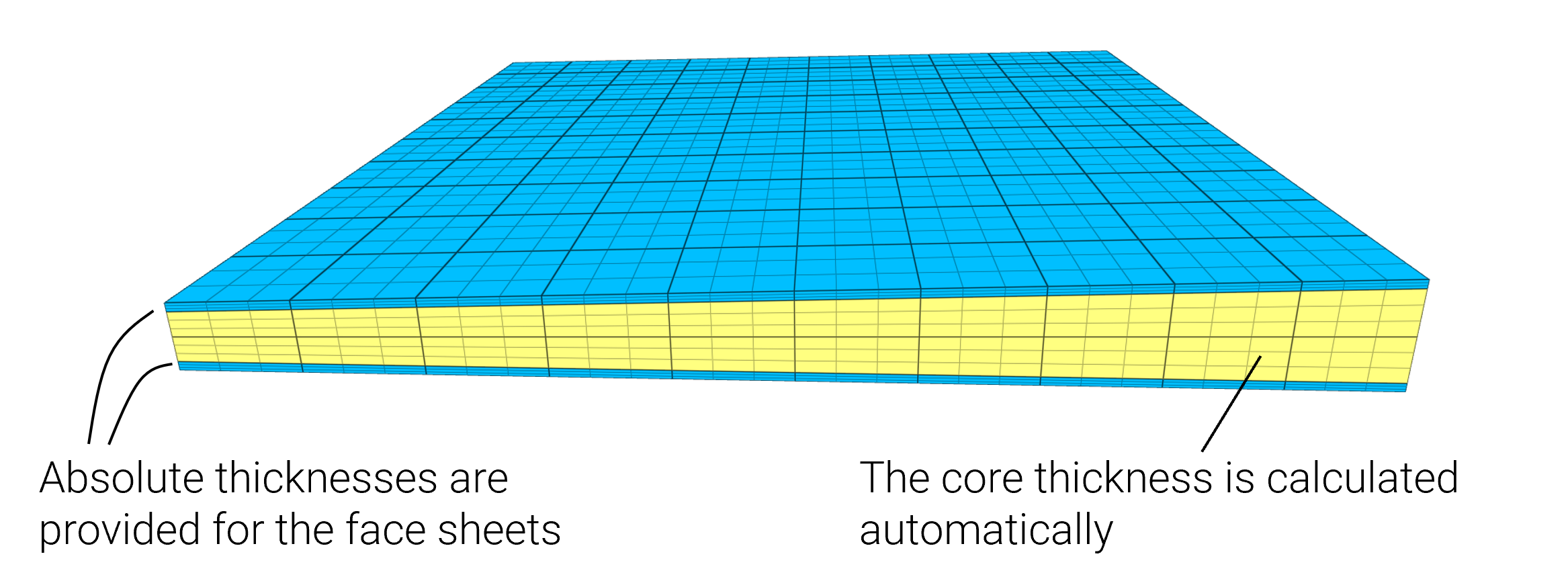
Absolute thicknesses (absolute=1) are typically used when modeling structures with two face layers and a core, where the face layers have fixed thicknesses. Absolute thicknesses are then specified for the face layers and 0 for the core. 0 means that the core layer thickness is defined as the original part thickness minus face sheet thicknesses.

Example
Subdivide a part into multiple layers

Example of how a solid component can be replaced by a layered structure.


*INCLUDE
mesh.k
*PARAMETER
cid = 1, "Command ID"
pid = 1, "Part ID"
tid = 2, "Table ID"
xf = 20, "x-coordinate front face"
yf =-496, "y-coordinate front face"
zf = 1495, "z-coordinate front face"
*SUBDIVIDE_PART_THICKNESS
"replace steel with layered structure"
[%cid]
[%pid], [%tid], [%xf], [%yf], [%zf]
#
# Columns:
# (1) Layer ID
# (2) Part ID
# (3) Thickness fraction
# (4) Number of elements
# (5) Merge flag
*TABLE
[%tid], 5
1, 10, 0.1, 1, 1
2, 11, 0.1, 1, 1
3, 10, 0.1, 1, 1
4, 11, 0.1, 1, 1
5, 10, 0.1, 1, 1
6, 11, 0.1, 1, 0
7, 12, 0.4, 2, 0
#
*MAT_RIGID
"dummy"
1, 1000.0
*MAT_ELASTIC
"laminate"
2, 1500.0, 50.0e9, 0.2
*MAT_ELASTIC
"aluminium"
3, 2700.0, 70.0e9, 0.3
#
*PART
"dummy"
1, 1
"ply 1"
10, 2
"ply 2"
11, 2
"aluminium"
12, 3
*END
Absolute face sheet thicknesses

Example of a sandwich structure where the face sheets have a fixed thickness and the core a varying thickness.


*PARAMETER
cid = 2, "Command ID"
pid = 2, "Part ID"
tid = 20, "Table ID"
xf = 0.5, "x-coordinate front face"
yf = 0.5, "y-coordinate front face"
zf = 0.04, "z-coordinate front face"
tf = 0.008, "face sheet thickness"
absolute = 1, "absolute thickness flag"
*COMPONENT_BOX_IRREGULAR
"base mesh"
1, [%pid], 10, 10, 1
0, 0, -0.03, 1, 0, -0.05
1, 1, -0.05, 0, 1, -0.03
0, 0, 0.03, 1, 0, 0.05
1, 1, 0.05, 0, 1, 0.03
*SUBDIVIDE_PART_THICKNESS
"sandwich structure"
[%cid]
[%pid], [%tid], [%xf], [%yf], [%zf], [%absolute]
#
# Columns:
# (1) Layer ID
# (2) Part ID
# (3) Absolute thickness
# (4) Number of elements
# (5) Merge flag
*TABLE
[%tid], 5
1, 3, [%tf], 1, 1
3, 2, 0, 2, 1
4, 3, [%tf], 1, 1
*CHANGE_P-ORDER
ALL, 0, 3
#
*MAT_ELASTIC
"core"
2, 100.0, 1.0e8, 0.2
*MAT_ELASTIC
"face"
3, 2700.0, 70.0e9, 0.3
#
*PART
"core"
2, 2
"face"
3, 3
*END