VULNERABLE_AREA_ASSESSMENT
Loads
Beta command
This command is in the beta stage and the format may change over time.
"Optional title"
coid, gid
entype${}_a$, enid${}_a$, entype${}_v$, enid${}_v$, tid, $RHA_c$, cid${}_{RHAc}$, $v_{imp}$
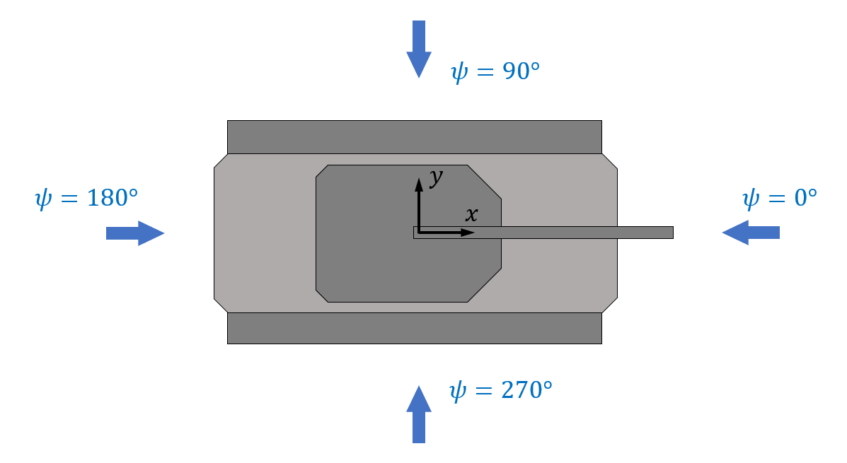
$\psi_0$, $\psi_1$, $N_{\psi}$, $\theta_0$, $\theta_1$, $N_{\theta}$, $D_p$
cid${}_{\phi def}$, $tol$, $\Delta_{hit}$
Parameter definition
Description
This command is primarily a tool that can be used to evaluate the ballistic protection level of armoured vehicles. It is not based on any Finite Element calculations, but uses simplified material and geometric assumptions to quickly estimate the ballistic protection at many thousands of hit spots. It is assumed that the threat follows a straight path through the armour and that that the protective performance of the different materials can be expressed in terms of specific relative RHA equivalence.
The RHA equivalent penetration capacity of the threat is either defined with the parameter $RHA_c$, or with a penetration capacity CURVE cid${}_{RHAc}$ + an impact velocity $v_{imp}$. (The threat specific curve specifies the RHA equivalent penetraton capacity versus impact velocity.)
By default $RHA_c$ defines the distance the threat can penetrate the target material before being stopped. The threat is assumed to follow a straight line and, hence, the effective armour thickness versus impact angle $\phi$ is scaled by a factor $1/\mathrm{cos}(\phi)$.
The larger impact angle, the less armour is needed to stop the threat. The default critical armour thickness versus impact angle $h(\phi)$ becomes:
$\displaystyle{h(\phi) = RHA_c \cdot \mathrm{cos}(\phi)}$
In reality the impact angle effect can be quite different, especially if the the threat is disturbed enough to ricochet or significantly change its path. This tool always assumes a straight penetration path. However, the real impact angle influence on the penetration capacity can still be taken into account. It is done by providing a CURVE cid${}_{\phi def}$ specifying the relative reduction in penetration capacity versus impact angle. This CURVE will then replace the default $\mathrm{cos}(\phi)$ relationship between impact angle and penetration capacity.
The command references to a TABLE listing the specific RHA equivalence (RHA equivialence per unit thickness) of the armour materials. The specific RHA equivalence of each material can be complemented with optional parameters defining edge effects, local softening in heat affected zones (see INITIAL_STATE_HAZ) and an optional material specific impact angle dependency.
The local specific RHA equivalence at a point on (or inside) the armour is obtained by averaging the material properties in a circular region perpendicular to the shooting direction. The radius of this region is determined by the impacted material's sensitivity to edge effects. Four simple examples are given below. The target material ID's are 100 (grey) and 200 (orange). Accounting for edge effects ($R_{edge} > 0$) has a significant effect on the computational effort.
The parameter $D_p$ needs to be defined in order to capture edge effects if the projectile impacts at gaps in the armour. A resistance will only be predicted if the distance between the projectile path and the armour is smaller than $D_p/2$.
The specific RHA equivalence integrated along the threat path through the armour renders a local RHA equivalent armour thickness $RHA_l$.
This value is compared to the critical armour thickness $RHA_c$ and a damage parameter is defined as:
$\displaystyle{D = \frac{RHA_c}{RHA_l}}$
$D \geq 1$ means that the armour will be perforated at the specific location for the given firing direction.
If the GEOMETRY ID gid is defined, then the calculations will be limited to the the elements enclosed by that geometry.
Example
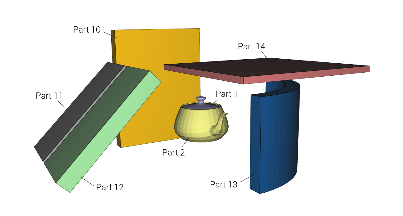
Ballistically protected teapot
A simple example of a protected teapot. The critical armour thickness is 20mm (threat dependent parameter). That is, the teapot will be damaged if it is shot at from a direction and location where the RHA equivalent armour thickness is less than 20mm.
We choose to test the protection in 10 horizontal and 3 in vertical angles. This brings us to a total of 30 different shooting directions. In each of these directions a dense grid of hit spots will be tested. A damage value will be calculated for each one of these hit spots. $D=0$ means that the armour is infinitiely thick, $D=0.5$ corresponds to an RHA equivalent thickness that is twice as large as needed to protect the teapot and $D=1$ is the limit where the protection is perforated.
The grids of damage values are used to generate damage maps. These maps visualize the armour performance in the different firing directions.