Validation - Close-Range Blast Loading
Introduction
This document presents validation tests on close-range blast loading modeled with the discrete particle module.
Numerical models of experiments are created and evaluated against the experimental results. Experimental data is gathered from several scientific studies reported in literature and common for the investigated cases is the scaled stand-off distance is less than one. All studies reported here have investigated the full interaction between high explosives, possibly sand and air and metal plate structures.
Version control
The tests presented in this document are subjected to version control, meaning that the models are run and evaluated prior to release of a new solver. This document is updated in conjunction with official releases of the software.
Discrete particle module
For close-range blast loading applications, a discrete particle-based approach is used to treat high explosives, air, and sand. All three particle types can interact in a simulation. The particles interact with structures represented by finite elements. Since the method is particle-based, the contact treatment is very efficient compared to the coupled Eulerian-Lagrangian analyses. The particle-based approach is applicable for close-range blast loading applications, where the scaled stand-off distance is less than two.
The discrete particle module comes with several calibrated explosives, presented in detail and with verification in the document "Verification - Calibrated Explosives". Sand is available as either dry or wet. The dry sand is modeled with a density of 1620  and is configured with a friction constant, while the wet sand has a density of 2020
  and is configured with both friction and damping. The wet sand is designed for fully saturated sand (moisture content > 20%).
CFD method
Additonally, the airblast tests which do not contain any sand are modelled with the CFD method for comparison. The CFD solver bridges the gap between Discrete Particles (applicable for close range blast and contact detonations) and the semi-empirical pressure-time history curves in *LOAD_AIR_BLAST (suitable for large stand-off distances).
Overview of tests
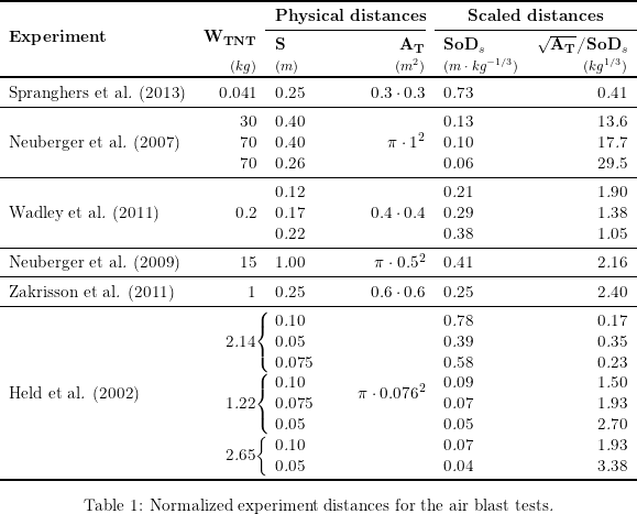
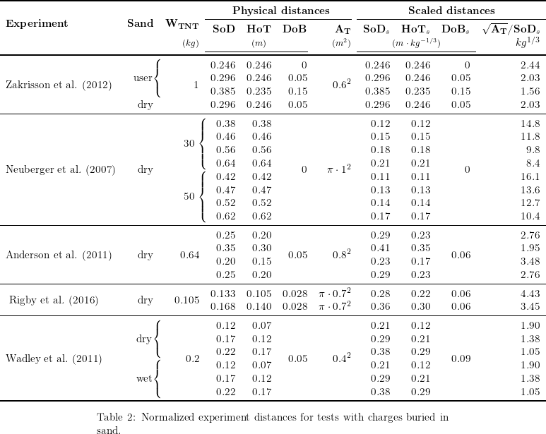
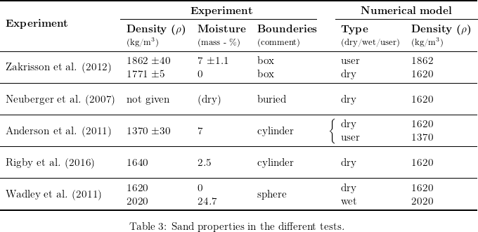
Comparable conditions in the tests have been normalized using the Hopkinson scaling method: Each parameter has been divided by the cube root of the charge mass ( ). For the experiments that used explosives other than TNT, the TNT equivalent was calculated prior to normalization. The normalized conditions for the air blast tests are showed in Table 1 while the tests with charges buried in sand is presented in Table 2. The density and moisture of the different sand types used in the experiments are displayed in Table 3. Even though the features of the sand are decisive, the two presets are mainly used. The density is however adjusted to match the density of the sand used in the experiments.
A. Neuberger et al. (2007)
A. Neuberger et al. (2007)
Scaling the Response of Circular Plates Subjected to Large and Close-Range Spherical Explosions
In this investigation the results from Neuberger et al (2007) are compared with numerical results from simulations. These tests consider circular plates subjected to large and close-range blast loading from spherical TNT charges. Part I of the original investigation treats explosions in air whereas Part II considers buried charges. A total of 22 different tests are investigated, configured as described in Table 1. Part I and II are used to distinguish between the articles given in the references. Figure 1 shows the two different models used in this investigation: the air blast model and the model for buried charges.
/Neuberger_2007_setup.png)
/longtable.png)
The target plate is modeled with material data from the referenced article and the frame is modeled as rigid. All cases are modeled with quarter symmetry and a total of 500k discrete particles. Air is included in the air blast tests while omitted in the test with a buried charge. There is no information regarding the density of the dry sand used in the experiments so the preset "dry" was selected with the default density.
The maximum central deflection of the plates was measured during the experiments. A comparison between the numerical and experimental results is given in Table 2.
/longtable01.png)
A convergence study regarding the number of discrete particles used was done for Test 1 and Test 7 with results showed in Figure 2 and 3. For version control, 500k particles are used.
/Neuberger_2007_test1_convergence.png)
/Neuberger_2007_test7_convergence.png)
The maximum central deflection of the plates from the CFD method was conducted for test 1-6. A comparison between the numerical and experimental results is given in Table 3.
/longtable02.png)
A convergence study regarding the number of CFD cells was done for Test 1 with results showed in Figure 4. For version control, 0.5 cm sized cells are used.
/Neuberger_2007_test1_convergence_cfd.png)
References
1 - A. Neuberger, S. Peles, D. Rittel, Scaling the Response of Circular Plates Subjected to Large and Close-range Spherical Explosions. Part I: Air-blast loading, International Journal of Impact Engineering, Volume 34, Issue 5, May 2007, Pages 859-873.
2 - A. Neuberger, S. Peles, D. Rittel, Scaling the Response of Circular Plates Subjected to Large and Close-range Spherical Explosions. Part II: Buried charges, International Journal of Impact Engineering, Volume 34, Issue 5, May 2007, Pages 874-882.
Tests
This benchmark is associated with 40 tests.
A. Neuberger et al. (2009)
A. Neuberger et al. (2009)
Springback of circular clamped armor steel plates subjected to spherical air-blast loading
In this investigation the results from Neuberger et al (2009) are compared with numerical results from simulations. The setup is a clamped, circular RHA steel plate exposed to blast loading in air from a spherical charge of 15 kg TNT at a stand-off distance of 1 m (centre of charge), see Figure 1.
/Neuberger_2009_setup.png)
The air and explosive charge are modeled with total of 1M particles and the steel plate is modeled in accordance to the referenced article. The edges of the target plate are fixed in XYZ which is a simplification of the clamped condition used in the experiment. Quarter symmetry is utilized to reduce computational time.
The maximum central deflection of the plates is measured during the experiments. The deflection found from the simulation is compared to the experimental result in Table 1 and Figure 2.
/longtable.png)
/Neuberger_2009_results.png)
An analysis of the sensitivity to the number of discrete particles used is presented in Figure 3. For version control, 1M particles are used.
/Neuberger_2009_convergence.png)
The maximum central deflection of the plates from the CFD method compared to the experimental results is given in Table 2 and Figure 4.
/longtable01.png)
/Neuberger_2009_results_cfd.png)
A convergence study regarding the number of CFD cells used is presented in Figure 5. For version control, 0.5 cm sized cells are used.
/Neuberger_2009_convergence_cfd.png)
Reference
1 - A. Neuberger, S. Peles, D. Rittel, Springback of circular clamped armor steel plates subjected to spherical air-blast loading, International Journal of Impact Engineering, Volume 36, Issue 1, January 2009, Pages 53-60.
2 - L. Olovsson, A.G. Hanssen, T. Børvik, M. Langseth, A particle-based approach to close-range blast loading, European Journal of Mechanics - A/Solids, Volume 29, Issue 1, January - February 2010, Pages 1-6.
Tests
This benchmark is associated with 11 tests.
B. Zakrisson et al. (2011)
B. Zakrisson et al. (2011)
Numerical Aimulations of Blast Loads and Structural Deformation from Near-Field Explosions
In this investigation the results from Zakrisson et al (2011) are compared with numerical results from simulations. The setup is a charge set off close to a steel plate. The peak displacement of the plate is measured. Two different blast loading cases are investigated: (1) a charge is located above the plate, and the plate rests freely on a stiff, cylindrical steel rig, and (2) a charge located within a steel pot beneath the plate, which is now fastened to the rig. The numerical models of both setups are displayed in Figure 1.
The aim of the second experiment is to replicate the conditions of the NATO Standard, where an explosive located in a steel pot is suggested as an alternative test method instead of positioning in sand. Please refer to the Zakrisson (2011) III benchmark for the experiments with sand included. Stand-off distances (SoD) are 250 mm and 255 mm, respectively, measured from the closest face of the charge to the plate. The charge is a 750g cylinder of m/46, with a diameter-to-height ratio of 3.
/Zakrisson_2011_setup.png)
The conditions in the experiments are presented in Table 1. In the experiments, different contact conditions between plate and rig was investigated, namely: dry and lubricated. The result from the dry tests is used for comparison with simulations.
/longtable.png)
The target plate of steel is modeled in accordance to the referenced literature while the rig and the steel pot is modeled as rigid. The air and explosive charge are modeled with a total of 500k particles which is determined from the sensitivity study in which quarter symmetry is being used.
The maximum deflection of the center part of the plate is measured during the experiments. A comparison between the numerical and experimental results is presented in Table 2 and Figure 2 and Figure 3.
/longtable01.png)
/Zakrisson_2011_II_air_blast_results.png)
/Zakrisson_2011_II_steel_pot_results.png)
The models sensitivity to the number of particles used is investigated with results presented in Figure 4 and 5. Quarter symmetry is used.
/Zakrisson_2011_II_air_blast_convergence.png)
/Zakrisson_2011_II_steel_pot_convergence.png)
The maximum deflection of the center part of the plate from the CFD method compared to the experimental results is presented in Table 3 and Figure 6 and Figure 7.
/longtable02.png)
/Zakrisson_2011_II_air_blast_results_cfd.png)
/Zakrisson_2011_II_steel_pot_results_cfd.png)
A convergence study regarding the number of CFD cells used is presented in Figure 8 and 9. Quarter symmetry is used. For version control, 0.40 cm sized cells are used.
/Zakrisson_2011_II_air_blast_convergence_cfd.png)
/Zakrisson_2011_II_steel_pot_convergence_cfd.png)
Reference
1 - Björn Zakrisson, Bengt Wikman, Hans-Å ke H$ \& $quot;{a}ggblad, Numerical simulations of blast loads and structural deformation from near-field explosions, International Journal of Impact Engineering, Volume 38, 2011, Pages 597-612.
Tests
This benchmark is associated with 20 tests.
B. Zakrisson et al. (2012)
B. Zakrisson et al. (2012)
Modelling and simulation of explosions in soil interacting with deformable structures
In this investigation the results from Zakrisson et al (2012) are compared with numerical results from simulations. The setup is a charge buried in a box filled with sand. A steel plate is located above the surface, and the peak displacement of the plate is measured. Stand-off distance (SoD) and depth of burial (DoB) is varied. The size of the box is adjusted to fit the charge at the different depths. The charge is a 750g cylinder of m/46, with a diameter-to-height ratio of 3. Experiment conditions are presented in Table 1 and an image of the model is displayed in Figure 1.
/longtable.png)
/Zakrisson_2012_setup.png)
The target plate of steel is modeled in accordance to the referenced literature while the rig is modeled as rigid. The explosive charge and sand are modeled with 1M particles and quarter symmetry is used. Air is not included in any of the tests.
A user-defined sand is employed for Run 1-3. The sand is calibrated based on Run 1 and then used in Run 2 and 3. For run 4, the preset "dry" is used. The density of the sand in each model is adjusted to match the density of the sand used in the corresponding experiment. The sand domain in the model is open at the sides but closed at the bottom.
The max displacement found from the numerical models are compared to the experimental results in Table 2 and Figure 2 - 5.
/longtable01.png)
/Zakrisson_2012_III_results_run_1.png)
/Zakrisson_2012_III_results_run_2.png)
/Zakrisson_2012_III_results_run_3.png)
/Zakrisson_2012_III_results_run_4.png)
A sensitivity study regarding the number of particles used is done for Run 1 with results presented in Figure 6. For version control, 1M particles are used.
/Zakrisson_2012_III_convergence.png)
Reference
1 - Björn Zakrisson, Hans-Å ke H$ \& $quot;{a}ggblad, P$ \& $quot;{a}r Jonsen, Modelling and simulation of explosions in soil interacting with deformable structures, Central European Journal of Engineering, Volume 2, 2012, Pages 532-550.
Tests
This benchmark is associated with 8 tests.
C. E. Anderson et al. (2011)
C. E. Anderson et al. (2011)
Mine Blast Loading Experiments
In this investigation the results from Anderson et al (2011) are compared with numerical results from simulations. The setup is a charge buried in sand. Sand is filled in a cylindrical cardboard container and a thick target plate of steel is located a certain distance above the sand surface. The impulse from the blast on the plate is measured. Stand-off distance (SoD) is varied, and both flat and V-shaped plates are used, as shown in Figure 1. The charge is a cylinder of 625 g comp. B, with a diameter-to-height ratio of 3, and its top 20 cm below the sand surface. Four different cases are investigated, with conditions as described in Table 1.
/longtable.png)
/Anderson_2011_setup.png)
The target plate is modeled as rigid with a density of ~ 7800 /mathmode.png) . The cardboard is simplified as ideal plastic with a yield limit of 3 MPa and a failure strain of 5%. All cases are modeled with quarter symmetry, 2M particles and without air. Set against other experiments with dry sand (Neuberger (2007), Wadley (2011), Zakrisson (2011) and Rigby (2016)), the sand density in this investigation is unusually low. The preset "dry" is selected with a reduced density to match the density of the sand used in the experiments.
. The cardboard is simplified as ideal plastic with a yield limit of 3 MPa and a failure strain of 5%. All cases are modeled with quarter symmetry, 2M particles and without air. Set against other experiments with dry sand (Neuberger (2007), Wadley (2011), Zakrisson (2011) and Rigby (2016)), the sand density in this investigation is unusually low. The preset "dry" is selected with a reduced density to match the density of the sand used in the experiments.
The impulse transfer to the target plate found in the numerical simulations are compared to the experimental results in Table 2 and Figure 2.
/longtable01.png)
/Anderson_2011_results.png)
A sensitivity study regarding the number of particles has been done for Run 1 with results showed in Figure 3. For version control, 2M particles are used.
/Anderson_2011_convergence.png)
Reference
1 - C. E. Anderson Jr., T. Behner, C. E. Weiss, S. Chocron, R. P. Bigger, Mine Blast Loading: Experiments and Simulations, International Journal of Impact Engineering, Volume 38, 2011, Pages 697-706.
Tests
This benchmark is associated with 10 tests.
H. N. G. Wadley et al. (2011)
H. N. G. Wadley et al. (2011)
A Discrete Particle Approach to simulate the Combined Effect of Blast and Sand Impact Loading of Steel Plates
In this investigation the results from Wadley et al (2011) are compared with numerical results from simulations. The se-up is a spherical charge of 150 g C4 at various stand-off distances (15, 20 or 25 cm) from a stainless steel AL-6XN target plate, see Figure 1. The stand-off distance (SoD) is measured from center of charge to plate face.
The tests were divided into three groups. In the first group the high explosive (HE) was set off in air. In the second group the HE charge was surrounded by a spherical shape of dry sand. In the third group, the HE charge was surrounded by wet sand.
/Wadley_2011_setup.png)
The target plate is modeled with material data from the referenced article while the frame is modeled as rigid. All cases are modeled with quarter symmetry, 1M discrete particles and with air included. The sand presets "dry" and "wet" are used without any change in density since they match the densities of the sand types used in the experiments.
After the experiments the permanent deflection of the center part of the plate was measured. A comparison between the experimental and numerical results is presented in Table 1.
/longtable.png)
The models sensitivity to the number of particles is investigated for the cases with the greatest stand-off distance (Test 3, 6 and 9). Results are presented in Figure 2, 3 and 4. For version control, 1M particles are used.
/Wadley_2011_convergence_air.png)
/Wadley_2011_convergence_dry.png)
/Wadley_2011_convergence_wet.png)
The permanent deflection of the center part of the plate from the CFD Method compared to the experimental results is presented in Table 2.
/longtable01.png)
The models sensitivity to the number of CFD cells is investigated for case 3. Results are presented in Figure 5. For version control, 0.50 cm sized cells are used.
/Wadley_2011_convergence_air_cfd.png)
Reference
1 - T. Børvik, L. Olovsson, A.G. Hanssen, K.P. Dharmasena, H. Hansson, H.N.G. Wadley, A discrete particle approach to simulate the combined effect of blast and sand impact loading of steel plates, Journal of the Mechanics and Physics of Solids, Volume 59, Issue 5, May 2011, Pages 940-958.
Tests
This benchmark is associated with 31 tests.
K. Spranghers et al. (2013)
K. Spranghers et al. (2013)
Numerical Simulation and Experimental Validation of the Dynamic Response of Aluminium Plates Under Free Air Explosions
In this investigation the results from Spranghers et al (2013) are compared with numerical results from simulations. The experiment includes a small spherical charge of 41 g C4 (including detonator) at a distance of 250 mm from an aluminium plate fixed in a frame, see Figure 1.
/Spranghers_2013_setup.png)
The aluminium target plate is modeled with material parameters from the referenced article and the frame is modeled as elastic with steel properties. The air and explosive charge are modeled with a total of 500 k discrete particles. Quarter symmetry is utilized to reduce the computational time.
The maximum initial peak deflections, measured at center of plate, are compared in Table 1 and Figure 2. The experimental average is based on three out of four tests. The fourth is excluded as it provided a more flexible response compared to the others.
/longtable.png)
/Spranghers_2012_result.png)
The numerical models sensitivity to the number of particles used has been investigated with results presented in Figure 3. For version control 500k particles are used.
/Spranghers_2012_convergence.png)
The maximum initial peak deflections at center of the plate from the CFD method is presented in Table 2 and Figure 4.
/longtable01.png)
/Spranghers_2012_result_cfd.png)
The numerical models sensitivity to the number CFD cells used is investigated with results presented in Figure 5. For version control, 0.30 cm sized cells are used.
/Spranghers_2012_convergence_cfd.png)
Reference
1 - K. Spranghers, I. Vasilakos, D. Lecompte, H. Sol, J. Vantomme, Numerical simulation and experimental validation of the dynamic response of aluminium plates under free air explosions, International Journal of Impact Engineering, Volume 54, April 2013, Pages 83-95.
Tests
This benchmark is associated with 10 tests.
M. Held (2002)
M. Held (2002)
Near Field Explosions
In this investigation the results from G.W. Weaver and W. P. Walters (1987) and M. Held (2002) are compared with numerical results from simulations. The experiments consist of an cylindrical explosive charge with length /mathmode.png) and diameter
and diameter /mathmode01.png) . A steel disc with thickness
. A steel disc with thickness /mathmode02.png) and diameter
and diameter /mathmode03.png) is located at a distance
is located at a distance /mathmode04.png) from the explosive charge with its axial direction aligned with the cylindrical charge. The test setup is presented in Figure 1.
from the explosive charge with its axial direction aligned with the cylindrical charge. The test setup is presented in Figure 1.
/Held_2002_setup.png)
The thickness of the disc, charge mass and the distance between the charge and the disc are altered in a total of 15 configurations, as presented in Table 1. A disc diameter of 152.4 mm and an Octol 78/22 charge with a length-to-diameter ratio of 2.16 is used in all cases.
/longtable.png)
The disc is modeled as a high strength steel and the explosive is modeled with 500k discrete particles. Air is not included in any test. Figure 2 shows the initial state of the simulation with the particle domain boundaries visualized with black lines.
/Held_2002_initial_state.png)
The maximum velocity and impulse found from the simulations are compared to experimental data in Table 2 and in Figure 3 and 4 below.
/longtable01.png)
/Held_2002_impulse.png)
/Held_2002_velocity.png)
Convergence was investigated for Test 9 with results presented in Figure 5. For version control, 500k particles are used.
/Held_2002_convergence.png)
The maximum velocity and impulse from the CFD method is compared to experimental data in Table 3 and in Figure 6 and 7 below.
/longtable02.png)
/Held_2002_impulse_cfd.png)
/Held_2002_velocity_cfd.png)
Convergence was investigated for Test 1 with results presented in Figure 8. For version control, 0.15 cm sized cells are used.
/Held_2002_convergence_cfd.png)
Reference
1 - M. Held, Near Field Explosions, Propellants, Explosives, Pyrotechnics 27, 2002, page 244-246.
2 - G.W. Weaver and W. P. Walters, Proximate Blast Loading of Structures, 10th International Symposium on Ballistics, San Diego, CA, 1987, page 27-29.
Tests
This benchmark is associated with 39 tests.
S. E. Rigby et al. (2016)
S. E. Rigby et al. (2016)
Measuring Spatial Pressure Distribution from Explosives Buried in Dry Leighton Buzzard Sand
In this investigation the results from Rigby et al (2016) are compared with numerical results from simulations. The experiments include a 78 g PE4 charge with a diameter-to-height ratio of 3, buried in sand at a depth of 28 mm, measured from top of charge to sand surface. The sand is in a cylindrical steel container with an inner diameter of 500 mm, wall thickness of 30 mm and a height of 375 mm. Pressure and specific impulse is measured at the surface of a circular steel target plate with a diameter of 1.4 m and a thickness of 0.1 m.
In the experiment, data were extracted by 17 Hopkinson pressure bars that were installed in the plate. The holes in which the bars are inserted forms a cross with four sets of four holes in perpendicular arrays around a center hole. An illustration of the experimental setup is presented in Figure 1.
/Rigby_2016_setup.png)
Two stand-off distances (SoD) are investigated, and five tests are executed at each distance. The test configurations are summarized in Table 1.
/longtable.png)
The sand preset "dry" is used with an adjusted density to match the density of the sand in the experiments. The sand and explosive are modeled with 4M particles and the models are run without air included.
The pressure and specific impulse is extracted from the simulations by nine sensors (*OUTPUT_SENSOR). Four sensors are positioned in two perpendicular arrays from a sensor at the center of the plate. The pressure and the specific impulse is averaged from the two sensors located at the same radial distance.
Numerical and experimental results of the specific impulse vs. radial position is presented in Figure 2 for Test 1-5 and Figure 3 for Test 6-10.
/Rigby_2016_impulse_140.png)
/Rigby_2016_impulse_105.png)
Reference
1 - S.E. Rigby, S.D. Fay, S.D. Clarke, A. Tyas, J.J. Reay, J.A. Warren, M. Gant, I, Elgy, Measuring spatial pressure distribution from explosives buried in dry Leighton Buzzard sand, International Journal of Impact Engineering, Volume 96, 2016, Pages 89-104.
Tests
This benchmark is associated with 2 tests.