BOLT_FAILURE

Contact and tied interfaces

*BOLT_FAILURE
"Optional title"
coid
pid, tid, $T_{fail}$, $S_{fail}$, $W_{fail}$

Parameter definition

Variable
Description
coid
Command ID
pid
Bolt part ID
tid
ID of table with bolt coordinates
$T_{fail}$
Tensile failure force
default: no failure
$S_{fail}$
Shear failure force
default: no failure
$W_{fail}$
Minimum absorbed energy prior to failure

Description

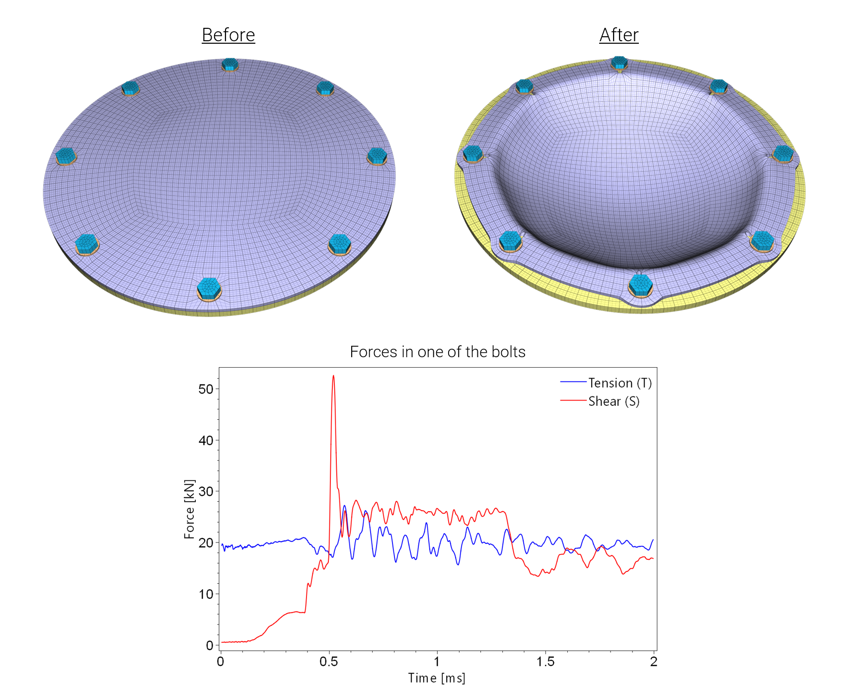
This command is used to define criteria for bolt failure. Bolts are identified through a list of coordinates in a TABLE. The coordinates are points on the surface of, or inside, the bolts. IMPETUS Solver will automatically identify the bolt elements and keep track of resultant forces and absorbed energies. Forces and energy levels are written to bolt_force.out.

A damage parameter $D$ is defined as:

$\displaystyle{ D = \mathrm{min} \left[ \sqrt{ \left( \frac{\mathrm{max}(0, T)}{T_{fail}}\right)^2 + \left( \frac{S}{S_{fail}} \right)^2 }, \frac{W}{W_{fail}} \right] }$

where $T$ and $S$ are the total tensile and shear forces in the bolt and $W$ is the absorbed energy (including elastic work). All bolt elements are eroded when damage reaches $D=1$. If no failure parameters are defined damage will not be computed. The command can then still be used to track and output force and energy levels.

An accurate calculation of the shear forces requires a relatively fine mesh. The shear zone (which can be extremely narrow) does not need to be resolved. However, as a rule of thumb, the element size in the axial direction of the bolt should not be larger than the thickness of the individual plates.

Example

Table with two bolts

A simple example showing how to list bolt coordinates in a TABLE.

*PARAMETER coid = 22, "Command ID" pid = 4, "Bolt part ID" tid = 100, "Table ID" T_fail = 2.0e5, "Tensile failure load" S_fail = 1.0e5, "Shear failure load" W_fail = 20.0, "Minimum energy absorption" x1 = 0.1, "X-coordinate of bolt 1" y1 = 0.2, "Y-coordinate of bolt 1" z1 = 0.3, "Z-coordinate of bolt 1" x2 = 0.4, "X-coordinate of bolt 2" y2 = 0.5, "Y-coordinate of bolt 2" z2 = 0.6, "Z-coordinate of bolt 2" *BOLT_FAILURE "bolt" [%coid] [%pid], [%tid], [%T_fail], [%S_fail], [%W_fail] *TABLE "bolt" [%tid] 1, [%x1], [%y1], [%z1] 2, [%x2], [%y2], [%z2]
Pressure loaded plate

In this example (complete input below) a bolted circular plate is exposed to a constant pressure load. The model runs in two steps. In Step 1 the bolts are pre-loaded using PRESTRESS_BOLT. The pressure is applied in Step 2.

A TABLE (ID=100) is used to define the location of the bolt holes (TRIM_HOLE). The same table is used by the commands COMPONENT_BOLT and BOLT_FAILURE. Note that BOLT_FAILURE only uses the first four columns of data in the table (bolt ID and location).

common.k (commands and parameters used in both steps):

*PARAMETER Dp = 0.5, "plate diameter" Dh = 0.4, "hole diameter" hp = 0.005, "plate thickness" hf = 0.01, "frame thickness" Db = 0.016, "bolt diameter" fric = 0.3, "contact friction" # # --- BOLT TABLE --- # *TABLE "frame bolts" 100, 7 # Bolt ID, Pos X, Pos Y, Pos Z, Dir X, Dir Y, Dir Z 1, [(%Dp+%Dh)/4 * cos( 0)], [(%Dp+%Dh)/4 * sin( 0)], [%hp], 0, 0, -1 2, [(%Dp+%Dh)/4 * cos( 45)], [(%Dp+%Dh)/4 * sin( 45)], [%hp], 0, 0, -1 3, [(%Dp+%Dh)/4 * cos( 90)], [(%Dp+%Dh)/4 * sin( 90)], [%hp], 0, 0, -1 4, [(%Dp+%Dh)/4 * cos(135)], [(%Dp+%Dh)/4 * sin(135)], [%hp], 0, 0, -1 5, [(%Dp+%Dh)/4 * cos(180)], [(%Dp+%Dh)/4 * sin(180)], [%hp], 0, 0, -1 6, [(%Dp+%Dh)/4 * cos(225)], [(%Dp+%Dh)/4 * sin(225)], [%hp], 0, 0, -1 7, [(%Dp+%Dh)/4 * cos(270)], [(%Dp+%Dh)/4 * sin(270)], [%hp], 0, 0, -1 8, [(%Dp+%Dh)/4 * cos(305)], [(%Dp+%Dh)/4 * sin(305)], [%hp], 0, 0, -1 # # --- MATERIAL --- # *MAT_METAL "plate" 1, 2700.0, 70.0e9, 0.3 1 *FUNCTION 1 150.0e6 + 100.0e6 * (1 - exp(-5*epsp)) *MAT_RIGID "frame" 2, 7800.0 *MAT_METAL "bolt" 3, 7800.0, 210.0e9, 0.3 3 *FUNCTION 3 640.0e6 + 800.0e6 * epsp^0.3 # # --- PART --- # *PART "plate" 1, 1 "frame" 2, 2 "bolt" 3, 3 "nut" 4, 3 "washer" 5, 3 # # --- BC --- # *BC_MOTION "frame" 2 P, 2, XYZ, XYZ # # --- CONTACT --- # *CONTACT "all to all" 1 ALL, 0, ALL, 0, [%fric] *END

step_1/main_step_1.k (prestress bolts):

*UNIT_SYSTEM SI # # --- PARAMETERS and COMMANDS USED IN BOTH STEPS --- # *INCLUDE ../common.k # # --- PARAMETERS --- # *PARAMETER tend = 0.002, "termination time" sig = 100.0e6, "prestress level" # # --- TIME and OUTPUT --- # *TIME [%tend] *OUTPUT [%tend/10] 0, 0, ALL, 0 # # --- MESH --- # *COMPONENT_CYLINDER "plate" 1, 1, 1, 30 0, 0, 0, 0, 0, [%hp], [%Dp/2] *COMPONENT_PIPE "frame" 2, 2, 1, 120, 6 0, 0, [-%hf], 0, 0, 0, [%Dh/2], [%Dp/2] *TRIM_HOLE "bolt holes" 1 PS, 12, 100, [%Db+0.001], [%hp+%hf] *SET_PART 12 1, 2 *COMPONENT_BOLT "bolts" 1, 3, 4, 5, 5, 0, 100 [%Db], [%hp+%hf+0.02], [%hp+%hf], 0.002 *CHANGE_P-ORDER ALL, 0, 3 *SMOOTH_MESH ALL, 0, 45.0 # # --- PRESTRESS BOLT --- # *PRESTRESS_BOLT 3, 4, 999 *CURVE "bolt prestress" 999 0, 0 [%tend/2], [%sig] [%tend], [%sig] # # --- DAMPING --- # *LOAD_DAMPING ALL, 0, 1000 *FUNCTION 1000 1.0e4 *END

step_2/main_step_2.k (pressure load on plate):

*UNIT_SYSTEM SI # # --- PARAMETERS and COMMANDS USED IN BOTH STEPS --- # *INCLUDE ../common.k # # --- PARAMETERS --- # *PARAMETER tend = 0.002, "termination time" pressure = 3.0e6, "pressure load" T_fail = 150.0e3, "tensile failure force" S_fail = 100.0e3, "shear failure force" # # --- TIME and OUTPUT --- # *TIME [%tend] # # --- BOLT FORCES --- # *BOLT_FAILURE "frame bolt" 1 3, 100, [%T_fail], [%S_fail] # # --- IMPORT RESULTS FROM STEP 1 --- # *INCLUDE ../step_1/impetus_state1.k *INCLUDE ../step_1/impetus_state_contact1.k *INCLUDE ../step_1/impetus_state_bolt1.k # # --- PRESSURE --- # *LOAD_PRESSURE "pressure on top of plate" 1 G, 1234, 2345 *GEOMETRY_SEED_COORDINATE "top surface of plate" 1234 0, 0, [%hp] *FUNCTION "pressure" 2345 %pressure *END