PRESTRESS_BLIND_HOLE_BOLT
Loads
pid${}_{bolt}$, pid${}_{plate}$, cid, $sf$, $t_{beg}$, $t_{end}$
Parameter definition
Description
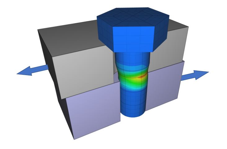
This command is used to prestress a set of bolts and to apply balancing forces to the surface of the holes in which the bolts are attached. pid${}_{bolt}$ is assumed to contain one or several bolts. pid${}_{plate}$ must have holes matching the bolts. The command identifies the discrete bolts and holes and creates bolt-hole pairs. The bolt shafts are prestressed with the axial stress defined by curve cid.
Example
Prestress blind hole bolt
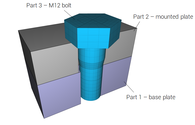
The following commands define an axial bolt shaft stress of 100MPa. The bolt is in part 3 and the threaded base plate in part 1. The applied shaft stress ramps up from 0 to 100MPa and is then held constant.
The OUTPUT command is defined to output state files for the complete model at termination. These state file are to be included in the next modeling stage, where the bolt is merged to the hole in the base plate:
impetus_state_boltX.k contains a MERGE command that locks bolt to the hole:
Each bolt hole pair has its own MERGE definition. As a consequence merge.out will have one force history curve for each connection.