
GEOMETRY_COMPOSITE
Geometries
*GEOMETRY_COMPOSITE
"Optional title"
gid
gid${}_1$, ..., gid${}_8$
"Optional title"
gid
gid${}_1$, ..., gid${}_8$
Parameter definition
Variable
Description
gid
Geometry identification number
gid${}_1$, ..., gid${}_8$
Up to 8 sub-geometry ID's
Description
This command is used to combine up to eight sub-geometries into one composite geometry. A negative ID means that the region represented by the sub-geometry will be removed from the composite geometry.
Example
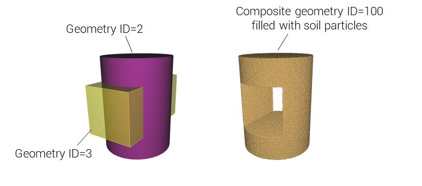
Composite geometry filled with soil
A composite geometry is defined by combining a GEOMETRY_PIPE with a GEOMETRY_BOX. The box is referenced with a negative ID and it cuts a hole in the cylinder defined by the pipe.
*UNIT_SYSTEM
SI
*PARTICLE_DOMAIN
0, 0, 1.0e6
0, 0, 0, 1, 1, 1
*PARTICLE_SOIL
1
DRY, 100
*GEOMETRY_COMPOSITE
100
2, -3
*GEOMETRY_PIPE
2
0.5, 0.5, 0.1, 0.5, 0.5, 0.9, 0.3
*GEOMETRY_BOX
3
0.1, 0.3, 0.3, 0.9, 0.7, 0.7
*END
Pressure loading
A square plate is subjected to a load pressure defined with a composite geometry. The composite geometry (ID=3) is created by combining the smaller box geometry (ID=2) with the larger box geometry (ID=1). The smaller box is referenced with a negative ID which removes it from the larger box.
*UNIT_SYSTEM
SI
*PARAMETER
%tend = 0.01, "Termination time"
*TIME
[%tend], 0, 0, 1e-4
*OUTPUT
[%tend/5]
*COMPONENT_BOX
1, 1, 10, 10, 1
-0.5, -0.5, -0.01, 0.5, 0.5, 0.0
*CHANGE_P-ORDER
P, 1, 3
*PART
1, 1
*MAT_RIGID
1, 1000
*GEOMETRY_BOX
1
-0.4, -0.4, 0.0, 0.4, 0.4, 0.1
*GEOMETRY_BOX
2
-0.2, -0.2, 0.0, 0.2, 0.2, 0.1
*GEOMETRY_COMPOSITE
3
1, -2
*LOAD_PRESSURE
1
G, 3, 1
*FUNCTION
1
1e4
*END