VAA
Loads
Beta command
This command is in the beta stage and the format may change over time.
"Optional title"
coid
entype${}_a$, enid${}_a$, entype${}_v$, enid${}_v$, tid${}_m$, $\delta_{ref}$, $\Delta_{hit}$
$\psi_0$, $\psi_1$, $N_{\psi}$, $\theta_0$, $\theta_1$, $N_{\theta}$
tid${}_f$
Parameter definition
Description
This command is a tool that can be used to evaluate the ballistic protection level of armoured vehicles. It is an enhanced version of VULNERABLE_AREA_ASSESSMENT. The main improvement is a more efficient and straightforward treatment of edge effects.
The methodology is not based on any Finite Element calculations, but uses simplified material and geometric assumptions to quickly estimate the ballistic protection at many thousands or millions of hit spots. It is assumed that the threat follows a straight path through the armour and that that the protective performance of the different materials can be expressed as critical thickness at normal impact.
$\delta_{ref}$ defines the critical thickness of a reference material at normal impact. It is used in the post-processor to quantify armour deficit or surplus at the hit spots. $\Delta_{hit}$ is the incremental distance between the hit spots.
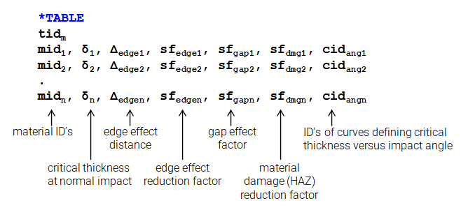
The command references to a TABLE (tid$_{}m$) listing the critical thicknesses of the armour materials. Optional parameters specifying capacity reductions near material edges, at gaps and in heat affected zones can also be provided. It is also possible to specify curves with material specific impact angle dependencies.
Default assumed relationship between critical material thickness and impact angle is based on "line of fire".
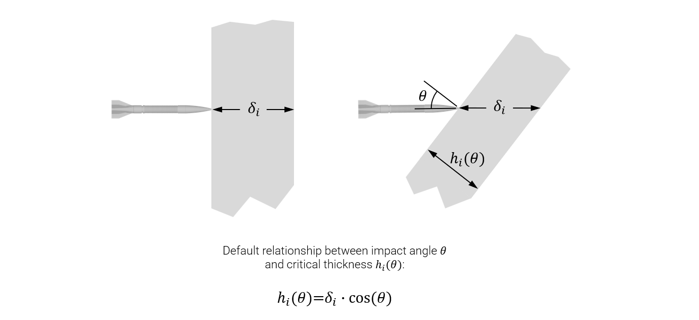
This relationship can be replaced by user defined curves for the different materials. The curves specify critical thickness versus impact angle.
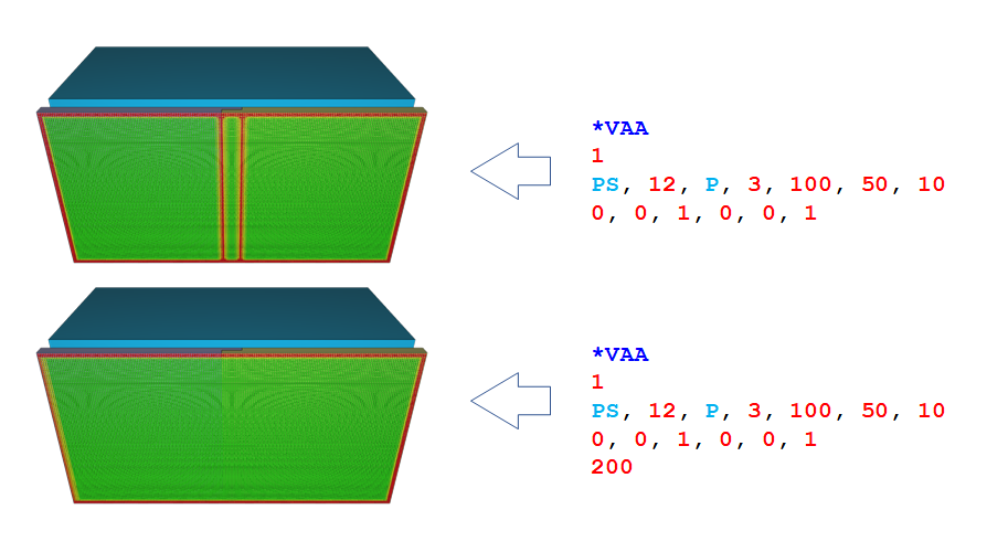
Materials can be assigned a reduced penetraion resistance near edges. For material $mid_i$ this is done through the parameters $\Delta_{edgei}$ and $sf_{edgei}$.
Gaps can have a negative effect on the protective capacity. By default, gaps are treated as edges. That is the same reduction will be applied to narrow gaps as to free edges. However, with $sf_{gapi}$ it is possible to control the magniude of the capacity reduction.
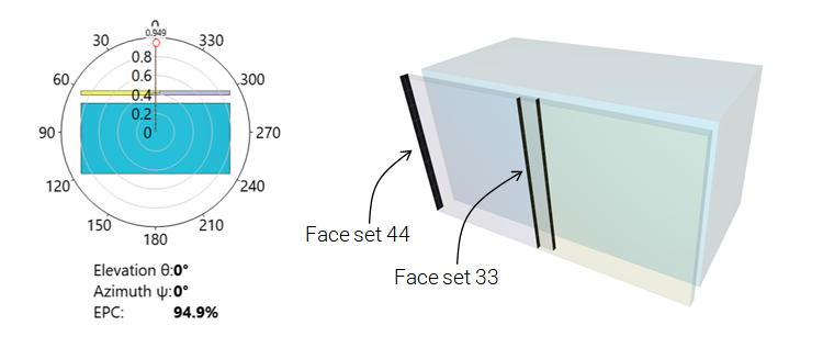
The optional TABLE tid${}_f$ is used define edge effect properties on face set level. Face set properties override the material specific edge effect properties in the material property table. An example is given below.
Reduced protective capacity in heat affected zones (typically after welding) can be accounted for by defining initial damage $D$ with the command INITIAL_STATE_HAZ. Having damage in an element using material $i$, the effective material thickness is reduced with a factor $(1 - D \cdot sf_{dmgi})$.
The vehicle is supposed to be oriented according to the figure below, with vertical direction along global $z$-axis.
Example
Edge effect properties by face set
This example shows how to override material specific edge effect properties on face set level. Note that edge effects are turned off completely by setting $\Delta_{edge}=-1$. In this example this is done for face set 33.