RIGID_BODY_JOINT

Rigid bodies
*RIGID_BODY_JOINT
"Optional title"
coid
entype${}_1$, enid${}_1$, entype${}_2$, enid${}_2$, bc${}_{tr}$, bc${}_{rot}$, csysid${}_1$, csysid${}_2$
$rx-$, $rx+$, $ry-$, $ry+$, $rz-$, $rz+$, $gap$, $\xi$, $pfac$
cid${}_{Tx}$, cid${}_{Ty}$, cid${}_{Tz}$, $T^f_x$, $T^f_y$, $T^f_z$, cid${}_{Fx}$, cid${}_{Fy}$, cid${}_{Fz}$
Parameter definition
VariableDescription
coid Joint ID
entype${}_1$ Entity type 1
options: P, CR
enid${}_1$ Entity identification number 1
entype${}_2$ Entity type 2
options: P, CR
enid${}_2$ Entity identification number 2
bc${}_{tr}$ Constrained translational degrees of freedom
options: X, Y, Z, XY, YZ, ZX, XYZ
bc${}_{rot}$ Constrained rotational degrees of freedom
options: X, Y, Z, XY, YZ, ZX, XYZ
csysid${}_1$ ID of coordinate system defining initial location of joint and orientation of Entity 1
default: global coordinates are used
csysid${}_2$ ID of coordinate system defining initial orientation of Entity 2
default: global coordinates are used
$rx-$ Maximum free rotation angle around x-axis in negative direction (deg)
$rx+$ Maximum free rotation angle around x-axis in positive direction
$ry-$ Maximum free rotation angle around y-axis in negative direction
$ry+$ Maximum free rotation angle around y-axis in positive direction
$rz-$ Maximum free rotation angle around z-axis in negative direction
$rz+$ Maximum free rotation angle around z-axis in positive direction
$gap$ Joint gap in all directions (clearance)
default: no gap
$\xi$ Fraction of critical damping of joint forces
default: 0.01
$pfac$ Optional user defined joint stiffness
default: automatically calculated
cid${}_{Tx}$ ID of CURVE describing torque as function of rotation around local x-axis (deg)
default: no rotational resistance
cid${}_{Ty}$ ID of CURVE describing torque as function of rotation around local y-axis
default: no rotational resistance
cid${}_{Tz}$ ID of CURVE describing torque as function of rotation around local z-axis
default: no rotational resistance
$T^f_x$ Friction torque when rotating around local x-axis
default: no rotational resistance
$T^f_y$ Friction torque when rotating around local y-axis
default: no rotational resistance
$T^f_z$ Friction torque when rotating around local z-axis
default: no rotational resistance
cid${}_{Fx}$ ID of CURVE describing force versus displacement in local x-direction)
default: no sliding resistance
cid${}_{Fy}$ ID of CURVE describing force versus displacement in local y-direction)
default: no sliding resistance
cid${}_{Fz}$ ID of CURVE describing force versus displacement in local z-direction)
default: no sliding resistance
Description

This command defines a joint between two rigid bodies or rigid connectors (see CONNECTOR_RIGID).

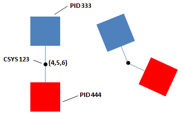
The joint is initially centered at the origin of csysid${}_1$. csysid${}_1$ also defines initial local directions in which the joint constraints are defined and forces/torques are output. csysid${}_2$ is used to define non-zero relative rotations at the initial state. csysid${}_2$ is only needed if the free rotations are limited or if rotational resistance is defined.

The joint rotation angle is defined as the rotation of enid${}_2$ minus the rotation of enid${}_1$. A non-zero initial rotation angle can be defined though csysid${}_1$ and csysid${}_2$.

Example
Joint

The following commands define a joint with ID 10 between the rigid parts with ID's 333 and 444. All rotations are free.

*RIGID_BODY_JOINT
"this is a title"
10
P, 333, P, 444, XYZ, 0, 123
*COORDINATE_SYSTEM_FIXED
123, 4.0, 5.0, 6.0
Joint between two rigid bodies